Page 559 - Hydrover-hydraulic-integrated-circuits-catalogue
P. 559

Electronic controls   61 SERIES

                                                                                                      H6102


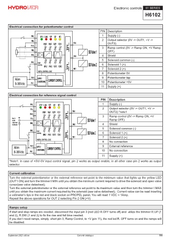
        Electrical connection for potentiometer control
                                                                       PIN Description
                                                                        1   Supply (-)
                                                                        2   Output selector (0V -> OUT1, +V ->
                                                                            OUT2)
                                                                        3   Ramp control (0V -> Ramp ON, +V Ramp
                                                                            OFF)
                                                                        4   Shield
                                                                        5   Solenoid common (-)
                                                                        6   Solenoid 1 (+)
                                                                        7   Solenoid 2 (+)
                                                                        8   Potentiometer 0V
                                                                        9   Potentiometer tap
                                                                       10   Potentiometer +5V
                                                                        11  Supply (+)

        Electrical connection for reference signal control
                                                                       PIN   Description
                                                                        1    Supply (-)
                                                                        2    Output selector (0V -> OUT1, +V ->
                                                                             OUT2) *note1
                                                                        3    Ramp control (0V -> Ramp ON, +V
                                                                             Ramp OFF)
                                                                        4    Shield
                                                                        5    Solenoid common (-)
                                                                        6    Solenoid 1 (+)
                                                                        7    Solenoid 2 (+)
                                                                        8    No connection
                                                                        9    External reference
                                                                        10   No connection

                                                                        11   Supply (+)
        *Note1: in case of +5V/-5V input control signal, pin 2 works as output enable, in all other case pin 2 works as output
        selector.

        Current calibration
        Turn the external potentiometer or the external reference set point to the minimum value that lights up the yellow LED
        (OUT1 ON) and turn the trimmer I MIN until you obtain the minimum current required to drive the solenoid and open valve
        cursor(see valve datasheet).
        Turn the external potentiometer or the external reference set point to its maximum value and then turn the trimmer I MAX
        until you obtain the maximum current required by the solenoid (see valve datasheet).  Current value can be read inserting
        a voltmeter’s tips in the red and black socket on PROPEL panel. You will read 1 VDC = 1Amp.
        Repeat the above operations for OUT 2 selecting Pin 2 ON (+V)


        Ramps setup
        If start and stop ramps are needed, disconnect the input pin 3 (red LED R.OFF turns off) and  utilize the trimmer R.UP (1
        and 2), R.DW (1 and 2) to fix the rise and fall time needed.
        If you don’t need ramps, simply  short pin 3, Ramp Control, to +V (pin 11), the red led R. OFF turns on and the ramps will
        be disabled.


       September 2023 edition                          General catalogue                                        559
   554   555   556   557   558   559   560   561   562   563   564