Page 558 - Hydrover-hydraulic-integrated-circuits-catalogue
P. 558
Electronic controls 61 SERIES
Double proportional control / undecal H6102
Introduction
This electronic control it’s been developed to drive a double solenoid proportional valve without integrated position
transducer. The device is enclosed in a “UNDECAL” plastic container with 11 pin standard circular connector (the typical
circular relays connector).
The output stage operates in PWM high-frequency modulation and produces a sinusoidal dither signal whose value can
be varied between 80 and 220Hz to fit most existing valve cursors.
The integrated current feedback allows a fine control versus solenoid temperature variations. The circuit also integrates
a short-circuit protection, which is signaled by its overloaded LED (O. LOAD) and protection for supply voltage inversion.
The green LED (SUPPLY) signals power supply presence, the two yellow LED (OUT A e OUT B) indicate the driving of
the solenoid.
Minimum current (I.MIN), maximum current (I.MAX), rise ramp (R.UP) and fall ramp (R.DW) can be calibrated with the
trimmer on frontal panel.
Ramps can be excluded shorting input RAMP CONTROL (3) to supply voltage (the red LED “R.OFF” lights).
You can drive the valve(s) wiring a 5 K Ohm or 10 K Ohm, potentiometer between pin 10 (+5V) and pin 8 (0V) with the tap
on pin 9 (ref.) or giving a reference set point between pin 9 (Ref.1) or pin 2 (Ref.2) and 0V pin 2 (-).
Control panel
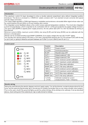
Control Description
SUPPLY Supply present
O.LOAD Overload protection
R.OFF Rise/fall ramp OFF
OUT.1 Output-solenoid 1 ON
OUT.2 Output-solenoid 2 ON
I MIN 1 OUT1 minimum current calibration
I MAX 1 OUT1 maximum current calibration
RAMP UP 1 OUT1 Rise ramp calibration
RAMP DW 1 OUT1 Fall ramp calibration
I MIN 2 OUT2 minimum current calibration
I MAX 2 OUT2 maximum current calibration
RAMP UP 2 OUT2 Rise ramp calibration
RAMP DW 2 OUT2 Fall ramp calibration
+ (1V/A) Voltmeter sockets for current
– (1V/A) measurement ( 1Volt = 1Ampere)
Electric wiring
Wiring the card following the electric diagram and don’t apply supply. Turn all the trimmer counterclockwise almost for ten
turns, set the external potentiometer tap or the set point to midway (remember that you are using a double valve system).
Turn on the card, check if the greed led lights up and the yellow led stay off (no driving to the valve(s)). If not as described
above, check wiring and if the external pot. tap is really turned to midway.
558 General catalogue September 2023 edition