Page 557 - Hydrover-hydraulic-integrated-circuits-catalogue
P. 557

Electronic controls   61 SERIES

                                                                                                      H6101


 Introduction  Current calibration
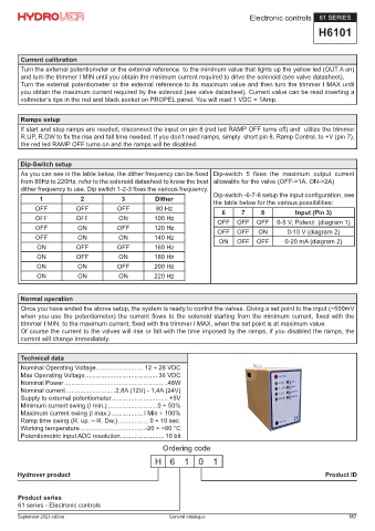
 This electronic control it’s been developed to drive a solenoid proportional valve without integrated position transducer.   Turn the external potentiometer or the external reference  to the minimum value that lights up the yellow led (OUT A on)
 The device is enclosed in a “OCTAL” plastic container with 8 pin standard circular connector (the typical circular relays   and turn the trimmer I MIN until you obtain the minimum current required to drive the solenoid (see valve datasheet).
 connector).  Turn the external potentiometer or the external reference to its maximum value and then turn the trimmer I MAX until
 The output stage operates in PWM high-frequency modulation and produces a sinusoidal dither signal whose value can   you obtain the maximum current required by the solenoid (see valve datasheet). Current value can be read inserting a
 be varied between 80 and 220Hz to fit most existing valve cursors.  voltmeter’s tips in the red and black socket on PROPEL panel. You will read 1 VDC = 1Amp.
 The integrated current feedback allows a fine control versus solenoid temperature variations. The circuit also integrates
 a short-circuit protection, which is signaled by its overloaded LED (O. LOAD) and protection for supply voltage inversion.
 The green LED (SUPPLY) signals power supply presence, the two yellow LED (OUT A e OUT B) indicate the driving of   Ramps setup
 the solenoid.  If start and stop ramps are needed, disconnect the input on pin 8 (red led RAMP OFF turns off) and  utilize the trimmer
 Minimum current (I.MIN), Maximum current (I.MAX), Rise ramp (R.UP) and Fall ramp (R.DW) can be calibrated with the   R.UP, R.DW to fix the rise and fall time needed. If you don’t need ramps, simply  short pin 8, Ramp Control, to +V (pin 7),
 trimmer on frontal panel.  the red led RAMP OFF turns on and the ramps will be disabled.
 Ramps can be excluded shorting input RAMP CONTROL (8) to supply voltage (the red LED  “R.OFF” lights).
 You can drive the valve wiring a 5 K Ohm or 10 K Ohm, potentiometer between pin 4 (+5V) and pin 1 (0V) with the tap on
 pin 3 (ref.) or giving a voltage (or current) reference between pin 3 (Ref.) and 0V pin 1 (-).  Dip-Switch setup
        As you can see in the table below, the dither frequency can be fixed  Dip-switch  5  fixes  the  maximum  output  current
        from 80Hz to 220Hz, refer to the solenoid datasheet to know the best  allowable for the valve (OFF->1A, ON->2A)
 Electrical wiring  dither frequency to use. Dip switch 1-2-3 fixes the various frequency.
 Wiring the card following the electric diagram and don’t apply supply. Turn all the trimmer counterclockwise almost for ten   1  2  3  Dither  Dip-switch -6-7-8 setup the input configuration, see
 turns, set the external potentiometer tap or the reference  to zero. Turn on the card, check if the greed led lights up and   the table below for the various possibilities:
 the yellow led stay off (no driving to the valve(s)). If not as described above, check wiring and if the external pot. tap is   OFF  OFF  OFF  80 Hz  6  7  8  Input (Pin 3)
 really turned to 0V.  OFF  OFF        ON         100 Hz              OFF   OFF   OFF    0-5 V, Potenz. (diagram 1)
 Diagram 1  OFF           ON          OFF         120 Hz              OFF   OFF    ON       0-10 V (diagram 2)
            OFF           ON           ON         140 Hz
 1.  Pot. 0V  ON         OFF          OFF         160 Hz               ON   OFF   OFF      0-20 mA (diagram 2)
 2.  Supply -
 3.  Pot. tap  ON        OFF           ON         180 Hz
 4.  Pot. +5V  ON         ON          OFF         200 Hz
 5.  Solenoid -  ON       ON           ON         220 Hz
 6.  Solenoid +
 7.  Supply +
 8.  Ramp control  Normal operation
        Once you have ended the above setup, the system is ready to control the valves. Giving a set point to the input (~500mV
        when you use the potentiometer) the current flows to the solenoid starting from the minimum current, fixed with the
        trimmer I MIN, to the maximum current, fixed with the trimmer I MAX, when the set point is at maximum value.
        Of course the current to the valves will rise or fall with the time imposed by the ramps, if you disabled the ramps, the
        current will change immediately.


 Diagram 2  Technical data
        Nominal Operating Voltage........................... 12 ÷ 28 VDC
 1.     Max Operating Voltage ......................................... 36 VDC
 2.  Supply -   Nominal Power ...........................................................48W
 3.  Reference (V or I)  Nominal current ............................2,8A (12V) - 1,4A (24V)
 4.     Supply to external potentiometer ................................ +5V
 5.  Solenoid -  Minimum current swing (I min.) ............................0 ÷ 50%
 6.  Solenoid +  Maximum current swing (I max.) ..................I Min ÷ 100%
 7.  Supply +  Ramp time swing (R. up. – R. Dw.) ................. 0 ÷ 10 sec.
 8.  Ramp control  Working temperature .....................................-20 ÷ +80 °C
        Potentiometric input ADC resolution ......................... 10 bit
                                                     Ordering code
                                                  H 6       1   0    1

       Hydrover product                                                                                 Product ID


       Product series
       61 series - Electronic controls

       September 2023 edition                          General catalogue                                        557
   552   553   554   555   556   557   558   559   560   561   562