
Page 703 - Hydrover-hydraulic-integrated-circuits-catalogue
P. 703
Electric Drives
Linear Motion and
Hydraulics
and Controls
Assembly Technologies
Service
Pneumatics
COMPONENTS
1/4
RE 18323-63/01.10
Replaces: RE 00162-02/01.06
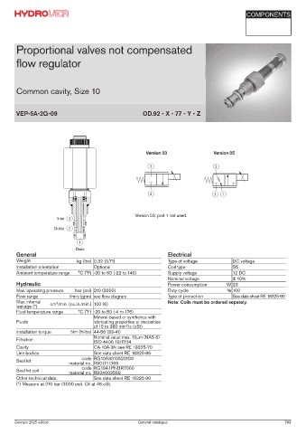
Proportional valves not compensated
flow regulator
Common cavity, Size 10
VEP-5A-2Q-09 OD.92 - X - 77 - Y - Z
Version 03 Version 05
Version 03: port 1 not used.
Inlet
Outlet
Drain
General Electrical
Weight kg (lbs) 0.32 (0.71) Type of voltage DC voltage
Installation orientation Optional Coil type S5
Ambient temperature range °C (°F) -30 to 60 (-22 to 140) Supply voltage 12 DC
Nominal voltage ± 10%
Hydraulic Power consumption W 23
Max. operating pressure bar (psi) 210 (3000) Duty cycle % 100
Flow range l/min.(gpm) see flow diagram Type of protection See data sheet RE 18325-90
Max. internal cm /min. (cu.in./min.) 100 (6) Note: Coils must be ordered sepately.
3
leakage (*)
Fluid temperature range °C (°F) -20 to 80 (-4 to 176)
Mineral-based or synthetics with
Fluids lubricating properties at viscosities
2
of 15 to 380 mm /s (cSt)
Installation torque Nm (ft-lbs) 44-56 (33-41)
Filtration Nominal value max. 10µm (NAS 8)
ISO 4406 19/17/14
Cavity CA-10A-3N see RE 18325-70
Line bodies See data sheet RE 18325-85
code RG10A3010520100
Seal kit material no. R901111369
code RG19A1PNBR7000
Seal kit coil
material no. R934003569
Other technical data See data sheet RE 18325-90
(*) Measure at 210 bar (3000 psi). Oil at 46 cSt.
Gennaio 2025 edition General catalogue 703