Page 596 - Hydrover-hydraulic-integrated-circuits-catalogue
P. 596

Multifunctional integrated circuits  97 SERIES

                                                                                                     H97101

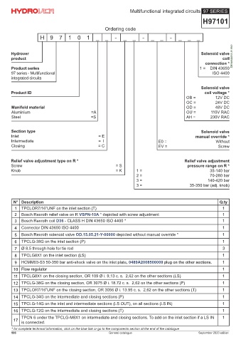
                                                     Ordering code
                     H 9      7    1   0    1   _    _    -   _    _   -    _   _    -   _    _   _


       Hydrover                                                                                     Solenoid valve
       product                                                                                                 coil Dimensions in mm
                                                                                                      connection *
       Product series                                                                               1 =  DIN 43650
       97 series - Multifunctional                                                                        ISO 4400
       integrated circuits

                                                                                                    Solenoid valve
       Product ID                                                                                     coil voltage *
                                                                                             OB =          12V DC
                                                                                             OC =          24V DC
       Manifold material                                                                     OD =          48V DC
       Aluminium                              =A                                             OU =        110V RAC
       Steel                                  =S                                             AH =        230V RAC


       Section type                                                                                 Solenoid valve
       Inlet                                      = E                                             manual override *
       Intermediate                               =  II                        E0 =                         Without
       Closing                                    = C                          EV =                          Screw


       Relief valve adjustment type on R *                                                  Relief valve adjustment
       Screw                                              = S                                 pressure range on R *
       Knob                                               = K       1 =                                  35-140 bar
                                                                    2 =                                  70-280 bar
                                                                    3 =                                 140-420 bar
                                                                    3 =                        35-350 bar (adj. knob)


        N° Description                                                                                       Q.ty
        1   TPCLOR7/16”UNF on the inlet section (T)                                                            1
        2   Bosch Rexroth relief valve on R VSPN-10A * depicted with screw adjustment                          1
        3   Bosch Rexroth coil D36 - CLASS H DIN 43650 ISO 4400 *                                              1
        4   Connector DIN 43650 ISO 4400                                                                       1
        5   Bosch Rexroth solenoid valve OD.15.05.21-Y-00000 depicted without manual override *                1

        6   TPCLG-38G on the inlet section (P)                                                                 1
        7   Ø 8,5 through hole for tie rod                                                                     3
        8   TPCLG8X1 on the inlet section (LS)                                                                 1
        9   HCMM03-S3 50-350 bar anti-shock valve on the inlet plate, 0489A2008500000 plug on the other sections.  1
        10 Flow regulator                                                                                      1
        11 TPCLG8X1 on the closing section, OR 109 Ø i. 9,13 c. s.  2,62 on the other sections (LS)            1
        12 TPCLG-38G on the closing section, OR 3075 Ø i. 18.72 c. s.  2,62 on the other sections (P)          1
        13 TPCLOR7/16”UNF on the closing section, OR 3056 Ø i. 13.95 c. s.  2,62 on the other sections (T)     1
        14 TPCLG-34G on the intermediate and closing sections (P)                                              1
        15 TPCLG-14G on the inlet and intermediate sections (LS OUT), on all sections (LS IN)                  1

        16 TPCLG-12G on the intermediate and closing sections (T)                                              1
            TPCN 6 under the TPCLG-M8X1 on intermediate and closing sections. To add on the inlet section if a LS IN   1
        17
            is connected.
       * for complete technical information, click on the blue link or go to the components section at the end of the catalogue
       596                                             General catalogue                           September 2023 edition
   591   592   593   594   595   596   597   598   599   600   601